

Robotic Welding Fixture Design: How to Build Fixtures for Repeatable Welds
A robot repeats whatever it is taught, including a bad starting position. If workpieces sit a few millimeters off, the torch will miss the same spot on every cycle. That is why robotic welding fixture design often does more for weld quality than the robot itself.
Welding fixtures hold components in the correct orientation so the welding process runs the same way on the first part and the ten-thousandth. This guide covers the design factors that produce consistent welds: locating and clamping, torch access, heat distortion, tolerance stack-up, and quick-change setups for high-mix production.
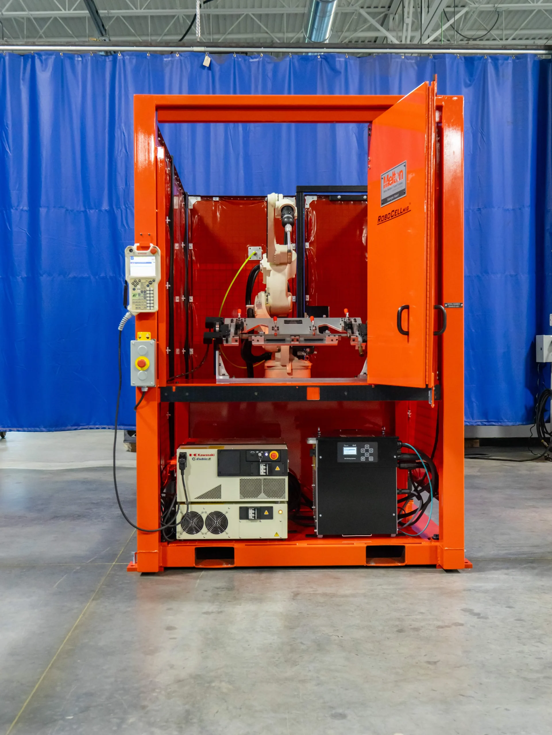
What Makes a Fixture Work in a Robotic Welding Cell?
A fixture, sometimes called a jig, holds, supports, and positions parts so the robot can weld them accurately. In manual welding, an operator can compensate for a part that sits slightly wrong. A robot cannot. Whether the cell runs gas metal arc welding with a MIG welding robot or gas tungsten arc welding with a TIG welding robot, the fixture is the foundation both processes depend on.
A good fixture design guide starts with the part’s weight, shape, and weld length, then works outward to the robot’s reach and the cell layout. The goal is accurate welds and consistent results without slowing down loading and unloading.
Locating and Clamping Fundamentals
Locating decides where a part sits, and clamping keeps it there. Locate first, then clamp, so the clamps don’t push the part out of position. Core elements include:
- Datum Features: Reference surfaces and holes that define the part’s position every time.
- Locating Pins and Stops: Hardened contact points that fix position and limit movement in each direction.
- Pneumatic Clamps: Fast, repeatable clamping force that integrates easily with robot controls.
- Part Presence Sensors: Confirmation that workpieces are positioned correctly before the arc starts.
Test clamp force on real parts so it holds each part firmly without deforming thin sections.
Designing for Torch Access
Even a perfectly located part fails if the torch cannot reach the joint. Designers have to think like the robot, so build the fixture in CAD alongside the robot model and run the weld path offline before any steel is cut.
Torch Angle and Reach
Every joint needs room for the push or drag angle the process requires, plus space for the nozzle and the arm’s swing. Clamps, tooling blocks, and mounted sensors are the usual culprits in blocking access to the welded part. Confirm that every seam can be reached in sequence without repositioning the part.
Cable and Wire Paths
Hoses and cables flex through the robot’s full range of motion. Keep them clear of clamps and pivot points so they don’t snag or wear.
Operator Access and Safety
Loading height and reach should be comfortable for operators. Safety features such as light curtains and barriers keep people separated from robot movement without blocking the load and unload routine.
Managing Heat Distortion and Warping
As a weld cools, the metal shrinks and pulls the weldment out of shape. Thin sections warp more than thick ones, and long welds accumulate more movement. Fixtures counter this in several ways:
- Balanced Clamping: Restrain movement on both sides of the joint.
- Heat Sinks: Copper or steel backing bars draw heat out of the weld zone.
- Weld Sequencing: Alternating locations spreads heat evenly across the part.
- Release Planning: Account for spring-back, since parts can relax once clamps open.
More clamping force is not always better, because it can lock in stress that appears after removal.
Controlling Part Tolerance Stack-Up
Every component arrives with its own variation, and those differences add up across an assembly. A few small deviations in stamped or cut parts can combine into a gap the robot was never programmed to weld.
Fixture Tolerances and Datums
Sound mechanical engineering starts by locating from the features that matter most to the finished assembly. Build the fixture more precisely than the parts it holds, and confirm how much joint gap the welding process can tolerate. Melton’s fixtures and tooling are designed from CAD models that check fit and function before anything is built.
Sensing and Supplier Review
A fixture cannot fix poor incoming parts. Touch sensing or seam tracking can adjust the path within set limits, and automated gauging systems can verify part dimensions before they reach the cell. Reviewing tolerances with suppliers early usually costs far less than redesigning a fixture later.
Quick-Change Fixtures for High-Mix Production
High-mix production adds a different challenge. The cell has to run many part numbers, and every changeover is lost production time. This is common in automotive manufacturing, where suppliers often run several variants on one line. Quick-change fixtures help:
- Modular Baseplates: Standard hole patterns allow fast reconfiguration.
- Dowel and Zero-Point Systems: Repeatable mounting returns each fixture to the same position without re-teaching the robot.
- Standard Interfaces: Common air and sensor connections reduce setup mistakes.
- Recipe-Based Programming: The robot program, fixture ID, and parameters load together.
The benefits are shorter setups, fewer errors, and a more cost-effective cell. Pairing quick-change fixtures with material handling automation delivers parts to the fixture in a consistent state, which supports repeatability.
Maintenance and Durability
Fixtures wear. Spatter builds up on pins and clamp faces, locating surfaces get dinged during loading, and pneumatic clamps lose force over time. A simple routine protects accuracy: clean spatter, inspect locators, check clamp pressure, and verify key dimensions on a schedule. Anti-spatter coatings and protective covers add durability. Slow drift in a fixture shows up as defects long before anything fails outright, so treat these checks as part of the quality system.
Fixtures Work Best as Part of the Whole Cell
The robot, positioner, sensors, safety features, and load/unload method all influence each other, so fixture design works best when it is planned with the full cell. In automotive production, for example, material handling automation can deliver parts to the fixture in a consistent state, which supports repeatability in robotic welding cells.
About Melton Machine & Control Company
Melton Machine & Control Company has designed and built automated systems since 1970. Based in Washington, Missouri, and 100% employee-owned, Melton handles design, build, and integration in-house, delivering robotic welding systems, fixtures, and tooling shaped around each customer’s parts.